
Purpose
This article explains how CyberSun SEMS typically sits inside the site network and how a technician should think about Ethernet, RS485, browser access and optional remote service paths.
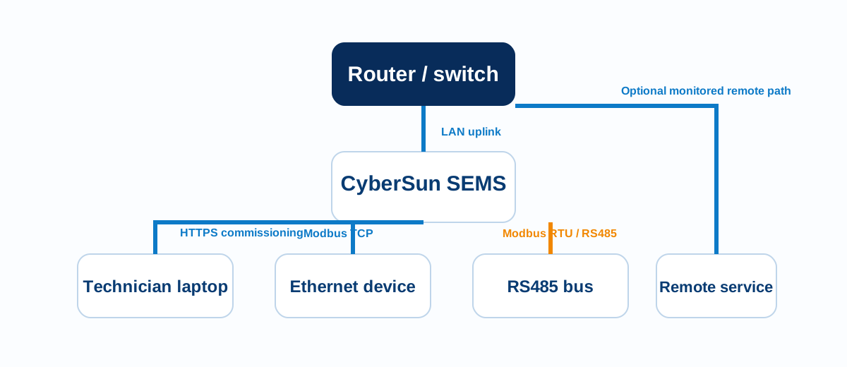
Core topology
In the currently inspected product generation, the main deployment building blocks are:
- SEMS controller on the local site network
- Ethernet-connected devices where Modbus TCP or web-managed networking is used
- RS485-connected devices where Modbus RTU is required
- A technician laptop on the same local subnet for commissioning
- Optional remote connectivity depending on project deployment
Ethernet in the current SEMS UI
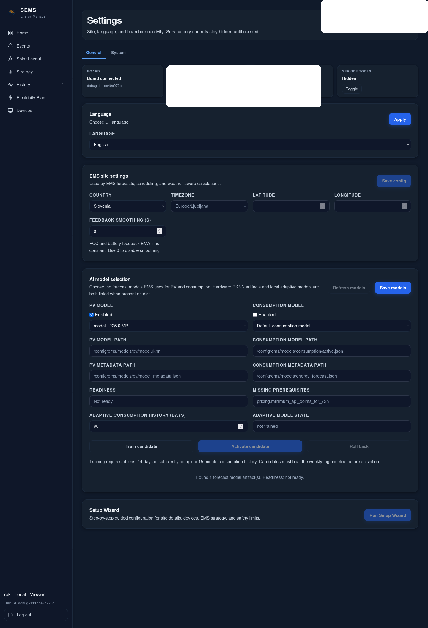
The current SEMS settings UI exposes:
eth0mode: DHCP or static- optional VLAN ID
- current IP, link state, gateway and DNS visibility
- static IPv4 address, mask, gateway and DNS fields
These fields are retrieved and saved through the board network settings API. Public guidance can therefore describe them as live product behavior.
Wi-Fi in the current SEMS UI
Where the board image and hardware expose Wi-Fi configuration, the current UI supports:
- role
ap - role
sta - role
apsta - client DHCP/static addressing
- visible-network scan
- AP SSID, password, IP/mask, band, country, security and channel fields
Do not assume Wi-Fi is part of every project topology. Ethernet remains the preferred commissioning path unless the deployment has an approved wireless design.
RS485 in the architecture
RS485 is used for field-bus style device communication where the target profile requires Modbus RTU. Public documentation may explain bus topology and validation method, but must not invent SEMS board pinouts or guaranteed connector presence across all hardware variants.
Recommended deployment principles
- Keep the SEMS controller reachable from a technician laptop over a known local path.
- Separate browser-access testing from device-polling validation.
- Verify each Modbus TCP endpoint independently before enabling any higher-level control policy.
- Verify each RS485 device independently before judging the whole bus.
- Document site addressing, unit IDs and protocol ownership during commissioning.
What is intentionally not stated here
This article does not publish:
- a universal factory-default IP address;
- a universal remote-access design;
- firewall port lists beyond what is visibly required by the current product UI;
- board-specific connector pinouts not verified in approved product documentation.
Was this helpful?
Did this article answer your question?
Feedback saved on this device. If you still need help, contact CyberSun support.