
Purpose
This guide explains the verified installation workflow for a CyberSun SEMS controller up to the point where the board can be powered and connected for network commissioning.
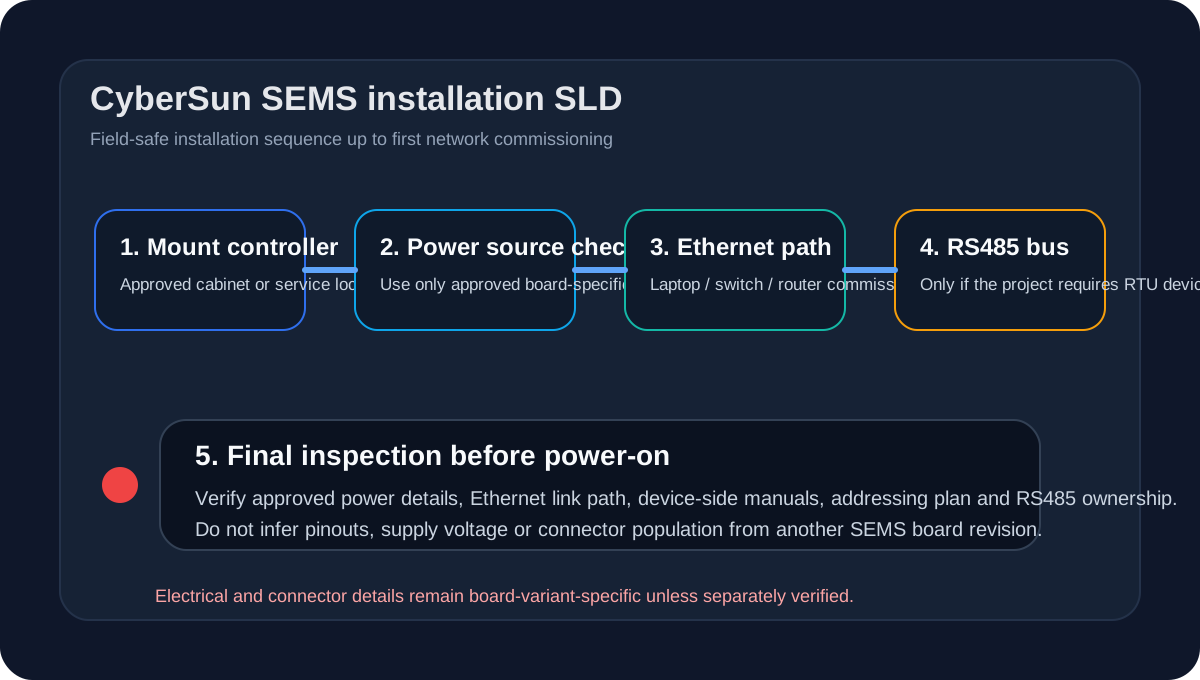
Electrical work must be performed by a qualified technician under the site’s approved electrical safety procedure. This article does not replace local electrical rules, lockout procedures or device manuals.
Before you begin
Confirm the following before mounting or powering the controller:
- the project has an approved installation location;
- the required SEMS hardware variant has been identified;
- the site has a confirmed power source for the board;
- the communication topology is known: Ethernet, RS485, or both;
- the required device-side manuals are available.
Required tools and materials
The public engineering sources support the following generic installation prerequisites:
- insulated hand tools suitable for the enclosure and mounting method;
- patch cable or approved Ethernet cabling for local commissioning;
- RS485 field cabling where required by the connected devices;
- a laptop on site for network discovery and first connection;
- site documentation for IP addressing, unit IDs and device ownership.
Local software and knowledge-base sources do not provide a complete public hardware manual with universal mounting hardware, pinouts, supply-voltage tables or connector population guarantees for every SEMS board variant. Use the board label, approved project BOM and current hardware documentation for unit-specific electrical details.
1. Controller placement
- Mount the controller in the approved cabinet, panel or service location.
- Leave physical access for Ethernet, RS485 and service inspection.
- Avoid mounting positions where cable strain or heat build-up would make service difficult.
- Confirm that the final position still allows the technician to inspect link status and reconnect the laptop if needed.
2. Power connection
- Verify the board-specific power requirement from the approved hardware source for the installed unit.
- Confirm correct polarity, protection and grounding requirements from the same source before wiring.
- Complete all pre-power checks before energizing the controller.
Do not derive a power-supply voltage or terminal pinout from screenshots, assumptions or another board revision. The engineering audit explicitly flagged board-level electrical specification coverage as incomplete for public documentation.
3. Ethernet connection
- Connect the commissioning Ethernet path to the verified active network interface for the installed unit.
- If the project uses a router or switch, confirm link state on the site side first.
- If static addressing will be used, prepare the expected IP plan before first login.
4. RS485 connection
- Confirm that the installed board variant exposes the required RS485 interface.
- Build the bus as a daisy chain, not as a star.
- Record the target device slave ID, baud rate, parity and stop bits for every device before software commissioning.
See RS485 wiring and commissioning for the approved public bus-level guidance.
5. Device-side readiness
Before the first power-up, verify that each field device is ready for communication:
- Modbus TCP devices have an IP address and reachable port
- Modbus RTU devices have a unique slave ID
- any vendor-side Modbus enable setting has been applied
- the installer knows which SEMS device profile will be used
6. Final inspection
Before powering the controller:
- inspect power wiring against the unit-specific approved source;
- confirm Ethernet cabling is connected and labeled;
- confirm RS485 polarity and addressing have been recorded;
- make sure the laptop can be connected to the same local network segment;
- prepare the commissioning checklist.
7. Power-up
- Energize the controller using the approved site procedure.
- Wait for the board to complete startup.
- Continue with Connecting to CyberSun SEMS.
Expected result
At the end of this stage:
- the controller is mounted;
- power has been applied safely;
- at least one commissioning network path is available;
- device communication parameters are known well enough to start the software workflow.
Was this helpful?
Did this article answer your question?
Feedback saved on this device. If you still need help, contact CyberSun support.